ChevyParts
My Garage
My Account
Cart
OEM Chevrolet Brake Light Switch
Brake Lamp Switch- Select Vehicle by Model
- Select Vehicle by VIN
Select Vehicle by Model
orMake
Model
Year
Select Vehicle by VIN
For the most accurate results, select vehicle by your VIN (Vehicle Identification Number).
79 Brake Light Switches found


Chevrolet Stoplamp Switch Part Number: 13583374
$13.79 MSRP: $25.90You Save: $12.11 (47%)Ships in 1-2 Business DaysProduct Specifications- Other Name: Sensor Assembly-Brake Pedal Position; Brake Light Switch; Sensor; Sensor, Brake


Chevrolet Clutch Switch Part Number: 13597428
$9.22 MSRP: $17.32You Save: $8.10 (47%)Ships in 1-2 Business DaysProduct Specifications- Other Name: Sensor Assembly-Brake Pedal Position; Clutch Pedal Position Switch; Brake Light Switch; Stoplamp Switch; Sensor, Stop Lamp Switch; Sensor, Engine Clutch; Sensor, Brake
- Replaced by: 13549051


Chevrolet Stoplamp Switch Part Number: 13579088
$13.17 MSRP: $24.74You Save: $11.57 (47%)Ships in 1-2 Business DaysProduct Specifications- Other Name: Sensor Assembly-Brake Pedal Position; Brake Light Switch; Sensor, Stop Lamp Switch; Sensor, Brake
- Replaced by: 13566315
- Replaces: 22774281


Chevrolet Stoplamp Switch Part Number: 20887894
$23.03 MSRP: $43.24You Save: $20.21 (47%)Ships in 1-2 Business DaysProduct Specifications- Other Name: Switch Assembly-Stop Lamp; Brake Light Switch; Switch, Stop Lamp Switch


Chevrolet Stoplamp Switch Part Number: 25799118
$38.89 MSRP: $118.13You Save: $79.24 (68%)Ships in 1-2 Business DaysProduct Specifications- Other Name: Sensor Kit, Brake Pedal Position; Brake Light Switch; Sensor Kit, Brake
- Replaces: 88982977


Chevrolet Stoplamp Switch Part Number: 13597419
$7.94 MSRP: $14.92You Save: $6.98 (47%)Ships in 1-2 Business DaysProduct Specifications- Other Name: Sensor Assembly-Brake Pedal Position; Brake Light Switch; Sensor, Stop Lamp Switch; Sensor, Brake
- Replaced by: 13549050


Chevrolet Release Valve Part Number: 10170430
$9.56 MSRP: $17.08You Save: $7.52 (45%)Ships in 1-3 Business DaysProduct Specifications- Other Name: Switch, Cruise Control; Brake Light Switch; Release Switch; Stoplamp Switch; Switch; Switch, Transmission Converter; Switch, Stop Lamp Switch
- Replaces: 10180531, 25551819


Chevrolet Stoplamp Switch Part Number: 15961519
$21.67 MSRP: $40.70You Save: $19.03 (47%)Ships in 1-2 Business DaysProduct Specifications- Other Name: Switch, Stop Lamp; Brake Light Switch; Switch, Stop Lamp Switch


Chevrolet Release Switch Part Number: 19330547
$18.52 MSRP: $34.78You Save: $16.26 (47%)Ships in 1-2 Business DaysProduct Specifications- Other Name: Switch, Cruise Control; Brake Light Switch; Stoplamp Switch; Switch; Switch, Stop Lamp Switch; Switch, Engine Brake
- Replaces: 25523463


Chevrolet Clutch Switch Part Number: 89047704
$18.29 MSRP: $34.33You Save: $16.04 (47%)Ships in 1-2 Business DaysProduct Specifications- Other Name: Sensor Kit, Brake Pedal Position; Brake Light Switch; Stoplamp Switch; Sensor Kit, Engine Clutch; Sensor Kit, Brake


Chevrolet Position Sensor Part Number: 13597416
$28.86 MSRP: $45.20You Save: $16.34 (37%)Ships in 1-3 Business DaysProduct Specifications- Other Name: Sensor Assembly-Brake Pedal Position; Clutch Switch; Sensor, Engine Clutch
- Replaced by: 13564158

Chevrolet Stoplamp Switch Part Number: 13579090
$8.79 MSRP: $16.50You Save: $7.71 (47%)Ships in 1-2 Business DaysProduct Specifications- Other Name: Sensor Assembly-Brake Pedal Position; Brake Light Switch; Sensor, Stop Lamp Switch; Sensor, Brake

Chevrolet Stoplamp Switch Part Number: 10180504
$28.42 MSRP: $53.38You Save: $24.96 (47%)Ships in 1-2 Business DaysProduct Specifications- Other Name: Switch, Stop Lamp Switch; Brake Light Switch

Chevrolet Brake Switch Part Number: 12450023
$10.05 MSRP: $18.88You Save: $8.83 (47%)Ships in 1-3 Business DaysProduct Specifications- Other Name: Switch Assembly-Stop Lamp; Brake Light Switch; Release Switch; Stoplamp Switch; Switch, Transmission Converter; Switch, Stop Lamp Switch

Chevrolet Stoplamp Switch Part Number: 89060201
$14.55 MSRP: $25.98You Save: $11.43 (44%)Ships in 1-3 Business DaysProduct Specifications- Other Name: Sensor Kit, Brake Pedal Position; Brake Light Switch
Chevrolet Stoplamp Switch Part Number: 19317473
$4.76 MSRP: $8.50You Save: $3.74 (44%)Ships in 1-3 Business DaysProduct Specifications- Other Name: Retainer, Brake Pedal; Brake Light Switch; Retainer, Cruise Control
Chevrolet Instrument Cluster Part Number: 25913321
$13.83 MSRP: $25.97You Save: $12.14 (47%)Ships in 1-2 Business DaysProduct Specifications- Other Name: Sensor Kit, Brake; Brake Light Switch; Stoplamp Switch

Chevrolet Stoplamp Switch Part Number: 15128745
$13.12 MSRP: $24.64You Save: $11.52 (47%)Ships in 1-2 Business DaysProduct Specifications- Other Name: Switch, Stop Lamp; Brake Light Switch; Switch; Switch, Stop Lamp Switch
- Replaces: 15741137, 15981543
Chevrolet Stoplamp Switch Part Number: 23102531
$21.14 MSRP: $39.68You Save: $18.54 (47%)Ships in 1-2 Business DaysProduct Specifications- Other Name: Sensor Assembly-Brake Pedal Position; Brake Light Switch; Sensor, Stop Lamp Switch; Sensor, Brake Pedal; Sensor, Brake
- Replaces: 22850788
Chevrolet Stoplamp Switch Part Number: 20929906
$14.45 MSRP: $22.63You Save: $8.18 (37%)Ships in 1-3 Business DaysProduct Specifications- Other Name: Sensor Kit, Brake; Brake Light Switch
| Page 1 of 4 |Next >
1-20 of 79 Results
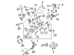
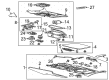
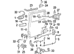
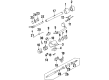
Chevrolet Brake Light Switch
Choose OEM Brake Light Switch, you're making the optimal decision for superior quality and perfect performance. You can feel confident because each component goes through stringent quality checks. Every part is carefully built to comply with Chevrolet's factory specifications. You'll enjoy a smooth, worry-free installation that fits just right. At ChevyPartsGiant.com, you'll find it easy to get top-quality OEM Chevrolet Brake Light Switch. You can shop at highly competitive prices and protect your budget. All our genuine Chevrolet parts include a dependable manufacturer's warranty. You'll also appreciate our straightforward return policy and swift delivery services for extra convenience.
Chevrolet Brake Light Switch Parts and Q&A
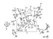
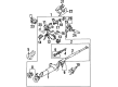
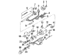
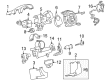
- Q: How to Replace and Install a Brake Light Switch on Chevrolet Colorado?A:First free and disconnect the stop lamp switch electrical connector before turning the switch counter-clockwise to pull it out from its bracket. Put the switch on the bracket so that the switch key fits into the plastic retention space easily. Pause the switch through the retainer until the pointed end enters the switch chamber entirely. A fully pushed Brake Pedal must make sure that the tip of the switch touches the brake arm before the switch's collapsing tip rotates. Twist the switch clockwise to push it securely at the end of the plastic holder. Use the stop lamp switch connector to establish power flow while checking for accurate switch functioning.
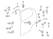
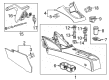
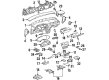
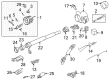
- Q: How to replace the Brake Light Switch on Chevrolet S10?A:Remove the Pushrod retainer from the brake pedal before you detach the stop lamp switch while also taking out the Pushrod from the pedal pin. Plugin the electric connector to the stop lamp switch before you put the stop lamp switch and Pushrod back onto the brake pedal pin. Finally fasten the Pushrod retainer back on the brake pedal pin to complete installation.


Related Chevrolet Parts
 Chevrolet Ignition Switch
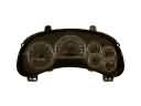 Chevrolet Instrument Cluster
 Chevrolet Door Jamb Switch
 Chevrolet Engine Control Module
 Chevrolet Fuel Pump Relay
 Chevrolet Headlight Relay
 Chevrolet Oil Pressure Switch
 Chevrolet Shift Solenoid
 Chevrolet ABS Relay
 Chevrolet Automatic Transmission Shift Position Sensor Switch
 Chevrolet Igniter
 Chevrolet Seat Heater Switch
Browse Chevrolet Brake Light Switch by Models
Nova S10 Colorado C10 Tahoe Cruze Malibu Camaro Equinox Impala SS SSR Avalanche Silverado 1500 Silverado 2500 HD Caprice Classic Cobalt Suburban Traverse Blazer HHR Sonic Tracker Volt El Camino K10 Spark Trax Trailblazer Astro Cavalier Corvette C20 Aveo Beretta Bolt EUV Bolt EV C1500 C2500 C30 C3500 Celebrity Chevette City Express Corsica Express 1500 Express 2500 Express 3500 G10 G20 G30 K1500 K20 K2500 K30 K3500 K5 Blazer Lumina Metro Monte Carlo Prizm S10 Blazer Silverado 2500 Sprint Uplander Venture Lumina APV Silverado 3500 Suburban 1500 Trailblazer EXT Avalanche 1500 Avalanche 2500 Aveo5 C10 Suburban C1500 Suburban C20 Suburban C2500 Suburban Captiva Sport Citation II Cruze Limited K10 Suburban K1500 Suburban K20 Suburban K2500 Suburban Malibu Limited R10 R10 Suburban R1500 Suburban R20 R20 Suburban R2500 R2500 Suburban R30 R3500 Silverado 1500 Classic Silverado 1500 HD Silverado 1500 HD Classic Silverado 1500 LD Silverado 1500 LTD Silverado 2500 HD Classic Silverado 3500 Classic Silverado 3500 HD Spectrum Suburban 2500 Suburban 3500 HD V10 V10 Suburban V1500 Suburban V20 V20 Suburban V2500 Suburban V30 V3500