ChevyParts
My Garage
My Account
Cart
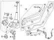
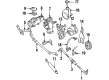
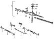
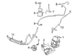
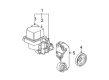
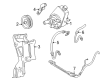
OEM GMC Power Steering Pump
Power Steering Pump Unit- Select Vehicle by Model
- Select Vehicle by VIN
Select Vehicle by Model
orMake
Model
Year
Select Vehicle by VIN
For the most accurate results, select vehicle by your VIN (Vehicle Identification Number).
93 Power Steering Pumps found

GMC Power Steering Pump Part Number: 84988708
$300.55 MSRP: $479.19You Save: $178.64 (38%)Ships in 1-2 Business DaysProduct Specifications- Other Name: Pump Assembly-Power Steering; Pump, Power Steering
- Replaces: 23121750

GMC Power Steering Pump Part Number: 26069033
$468.51 MSRP: $917.30You Save: $448.79 (49%)Ships in 1-2 Business DaysProduct Specifications- Other Name: Pump, Power Steering
- Replaced by: 19420681

GMC Power Steering Pump Part Number: 26069031
$468.51 MSRP: $917.30You Save: $448.79 (49%)Ships in 1-2 Business DaysProduct Specifications- Other Name: Pump Assembly-Power Steering
- Replaced by: 19420681

GMC Power Steering Pump Part Number: 84983793
$185.81 MSRP: $292.37You Save: $106.56 (37%)Ships in 1-3 Business DaysProduct Specifications- Other Name: Pump Assembly-Power Steering; Pump, Power Steering
- Replaced by: 86564077
GMC Power Steering Pump Part Number: 26069036
$246.77 MSRP: $388.28You Save: $141.51 (37%)Ships in 1-3 Business DaysProduct Specifications- Other Name: Pump Assembly-Power Steering

GMC Power Steering Pump Part Number: 19369081
$231.13 MSRP: $366.97You Save: $135.84 (38%)Ships in 1-2 Business DaysProduct Specifications- Other Name: Pump Kit, Power Steering
- Replaced by: 19433017

GMC Power Steering Pump Part Number: 84983791
$204.64 MSRP: $351.44You Save: $146.80 (42%)Product Specifications- Other Name: Pump Assembly-Power Steering; Pump, Power Steering
- Replaced by: 86563313
GMC Power Steering Pump Part Number: 26065181
$268.35 MSRP: $422.23You Save: $153.88 (37%)Ships in 1-3 Business DaysProduct Specifications- Other Name: Pump Assembly-Power Steering

GMC Power Steering Pump Part Number: 19420688
$449.33 MSRP: $710.16You Save: $260.83 (37%)Ships in 1-2 Business DaysProduct Specifications- Other Name: Pump Assembly, Power Steering; Pump, Power Steering
- Replaces: 88963603, 15267669, 15076612, 15909828, 20756710

GMC Power Steering Pump Part Number: 15752311
$165.15 MSRP: $259.86You Save: $94.71 (37%)Ships in 1-3 Business DaysProduct Specifications- Other Name: Pump Assembly-Power Steering

GMC Power Steering Pump Part Number: 26069070
$446.51 MSRP: $766.86You Save: $320.35 (42%)Ships in 1-2 Business DaysProduct Specifications- Other Name: Pump Assembly-Power Steering
- Replaced by: 84996212

GMC Power Steering Pump Part Number: 15749569
$240.91 MSRP: $379.05You Save: $138.14 (37%)Ships in 1-3 Business DaysProduct Specifications- Other Name: Pump, Power Steering
GMC Power Steering Pump Part Number: 88963609
$204.69 MSRP: $337.19You Save: $132.50 (40%)Ships in 1-2 Business DaysProduct Specifications- Other Name: Pump Kit, Power Steering; Pump, Power Steering

GMC Power Steering Pump Part Number: 26069038
$245.38 MSRP: $386.09You Save: $140.71 (37%)Ships in 1-3 Business DaysProduct Specifications- Replaced by: 19420685

GMC Power Steering Pump Part Number: 84983792
$181.37 MSRP: $285.37You Save: $104.00 (37%)Ships in 1-3 Business DaysProduct Specifications- Other Name: Pump Assembly-Power Steering; Pump, Power Steering
- Replaced by: 86564078

GMC Power Steering Pump Part Number: 26039621
$233.64 MSRP: $367.61You Save: $133.97 (37%)Ships in 1-3 Business DaysProduct Specifications- Other Name: Pump Assembly-Power Steering
- Replaced by: 15755161

GMC Power Steering Pump Part Number: 26043373
Product Specifications- Other Name: Pump Kit, Power Steering

GMC Power Steering Pump Part Number: 19420684
Product Specifications- Other Name: Pump Kit, Power Steering; Pump, Power Steering
- Replaces: 15267675, 15134705, 88963604, 15095941, 15909831

GMC Power Steering Pump Part Number: 19433012
$211.15 MSRP: $332.23You Save: $121.08 (37%)Product Specifications- Other Name: Pump Kit, Power Steering; Pump, Power Steering
- Replaces: 19369075, 26112229
GMC Power Steering Pump Part Number: 19420685
$245.38 MSRP: $386.09You Save: $140.71 (37%)Product Specifications- Other Name: Pump Kit, Power Steering; Pump, Power Steering
- Replaces: 26069038, 88963501, 26057289, 26057293
| Page 1 of 5 |Next >
1-20 of 93 Results
GMC Power Steering Pump
Want to cut long-term maintenance and repair costs? Choose OEM Power Steering Pump. Those parts deliver top durability you can trust. On our site, you'll find a huge catalog of genuine GMC parts. Prices are unbeatable, so you can keep more in your pocket. Every OEM GMC Power Steering Pump includes a manufacturer's warranty. You can also get an easy return policy that keeps buying risk free. Fast delivery, get your car on the road quickly. It's simple to search, compare, and order. Stop guessing about quality or fit. Order today and save with parts that last.
GMC Power Steering Pump Parts and Q&A
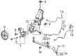
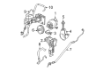
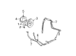
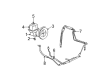
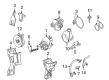
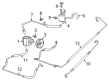
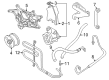
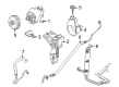
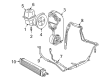
- Q: How to replace the power steering pump on GMC Acadia?A:Replace the Power Steering Pump by starting with fuel injector sight shield removal and emptying the remote power steering fluid reservoir through drainage which requires appropriate drain pans positioned beneath the vehicle. The Drive Belt must be dismantled after the steering gear heat shield and right side Catalytic Converter. Begin by disconnecting the power steering fluid reservoir outlet hose from the Power Steering Pump followed by removing the power steering gear inlet hose . Then take out the Power Steering Pump after removing its bolts . To install the Power Steering Pump insert it into the vehicle and tightening the Power Steering Pump bolts to 50 n.m (37 lb ft). After fitting along the power steering gear inlet hose to its Power Steering Pump location, use 27 n.m (20 lb ft) torque then attach the power steering fluid reservoir outlet hose to the Power Steering Pump. First wipe all remaining fluid from the vehicle and discard the drain pans before putting back the right side Catalytic Converter and steering gear heat shield and Drive Belt. The procedure ends by adding power steering fluid through a process of bleeding before installing the fuel injector sight shield.
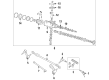
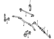
- Q: How to replace the power steering pump on 4.8L, 5.3L, and 6.0L engines on GMC Sierra 1500?A:The first step to replace power steering pumps for 4.8l, 5.3l, and 6.0l engines requires dealign the power steering pulley then lifting the vehicle. Proceed by removing the bolts securing the oil pan skid plate along with the skid plate when equipped. Position a drain pan underneath your vehicle. The power steering pressure hose needs to be detached from the pump underneath the car before lowering the car. After accessing the power steering return hoses to the pump with clamps (3,5) users should remove those components. Start by removing the lower intermediate shaft from the steering gear and then proceed with removing the bolt which attaches the rear bracket to the engine followed by the front pump bolts. After removal of the pump from the vehicle you need to remove the bracket that secures the pump at its rear. Installation requires attaching the bracket to the pump rear portion followed by tightening all rear bracket retaining nuts to 50 nm (37 ft. Lbs.). Secure the Power Steering Pump by installing a bolt which should be tightened to 50 nm (37 ft. Lbs.) at the engine end of the rear bracket. The bolt tightening process on the pump front should reach 50 nm (37 ft. Lbs.) after which the Power Steering Pump return hoses (2,4) can be installed with retaining clamps. Reposition the vehicle to rise it up and affix the power steering pressure hose to the pump while tightening the fitting to 28 nm (20 ft. Lbs.). Reinstall the oil pan skid plate after which secure the bolts to 20 nm (15 ft. Lbs.) until the vehicle rest on the ground. The technical process ends with reinstalling the intermediate shaft before adding power steering system fluid then performing a bleeding procedure.


Related GMC Parts
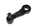 GMC Pitman Arm
 GMC Rack And Pinion
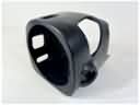 GMC Steering Column Cover
 GMC Center Link
 GMC Drag Link
 GMC Ignition Lock Assembly
 GMC Power Steering Assist Motor
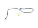 GMC Power Steering Hose
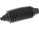 GMC Rack and Pinion Boot
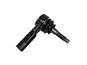 GMC Tie Rod
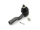 GMC Tie Rod End
 GMC Upper Steering Column Bearing
Browse GMC Power Steering Pump by Models
Acadia Sierra 1500 Yukon Canyon Sierra 2500 HD Terrain Envoy Sonoma Typhoon Syclone Caballero C1500 Envoy XL Envoy XUV Jimmy K1500 S15 S15 Jimmy Safari Savana 2500 Savana 3500 Sierra 2500 Sierra 3500 Acadia Limited C2500 C3500 G2500 K2500 K3500 P3500 Savana 1500 Yukon XL 1500 C1500 Suburban C2500 Suburban G1500 G3500 K1500 Suburban K2500 Suburban P2500 R1500 R1500 Suburban R2500 R2500 Suburban R3500 Sierra 1500 Classic Sierra 1500 HD Sierra 1500 HD Classic Sierra 2500 HD Classic Sierra 3500 Classic Sierra 3500 HD V1500 V1500 Suburban V2500 V2500 Suburban V3500 Yukon XL 2500