
Popular OEM Buick LeSabre Parts
- Body & Hardware Parts View More >
- Steering Parts View More >
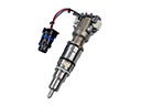
- Electrical Parts View More >
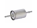
- Air & Fuel Delivery Parts View More >
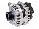
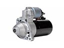
- Charging & Starting Parts View More >
- Engine Parts View More >
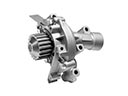
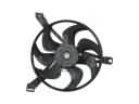
- Belts & Cooling Parts View More >
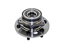
- Suspension Parts View More >
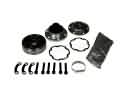
- Driveline & Axles Parts View More >
- Emission Control & Exhaust Parts View More >
- Transmission Parts View More >
- Brakes Parts View More >


Why Buy Genuine Buick LeSabre Parts From ChevyPartsGiant.com
Looking for real Buick LeSabre parts? ChevyPartsGiant.com may be a better choice to find genuine parts at wallet-friendly prices. We sell only OEM Buick LeSabre parts, ensuring perfect fit, reliability, and long-term performance. With our website, you can easily get access to the same parts found at local Buick stores. All components are produced by Buick and are exclusively fitted on Buick LeSabre automobiles. By shopping at our store, you can enjoy the quality of the Buick factory without the high prices of brick-and-mortar facilities. We achieve this because we are an online store operating at lower costs, which we pass on to you. We also have a user-friendly platform where you can find and order genuine Buick LeSabre parts swiftly. We are here to make your process of restoring a Buick LeSabre or dealing with simple repairs quick and inexpensive. We also make it easy to obtain Buick LeSabre parts at competitive shipping prices and a team of knowledgeable staff ready to take your order. Choose ChevyPartsGiant.com to save time and money, as well as keep your Buick LeSabre in the good condition.
Automotive history marks the Buick LeSabre as a noteworthy production because it originated in 1959 through its continued manufacturing until 2005 while advancing its technical capabilities and design elements. The original Buick LeSabre design was based on the 1951 GM Le Sabre show car which underwent substantial modifications predominantly in its engine and transmission systems. In 1972 Buick presented two engine options including the standard 350 V8 with 160 horsepower and the more robust 455 V8 with 250 horsepower showing engine technology progress. In 1986 the company introduced the front-wheel-drive H-chassis which led to better driving performance and enhanced handling abilities. The new model design presented a sleek appearance with sealed-beam headlights and an updated hood design. The front fenders received an updated design that contributed to a more streamlined vehicle appearance. The Buick LeSabre received modernized transmission systems that matched up with its engine developments while automatic transmissions grew better at shifting and consuming less fuel. The Buick LeSabre kept comfort and driving ease as its core principles while adding adjustable power steering with disc brakes when it entered production during 1971. Every vehicle maintains its manufacture-defined standards through genuine Buick LeSabre parts obtained straight from the producer because Buick remains committed to both quality and dependability. The Buick LeSabre has achieved its status as a dependable luxury car through its fundamental engineering combined with genuine components.
The three concerns that are categorized by engine management, starting security, and evaporative sealing, are found in the Buick LeSabre. In engine management, there may be stalling or misfiring during warm traffic in the LeSabre. Failure of a mass air flow sensor distorts airflow calculations and leans the mixtures. A loose crankshaft position sensor loses sync and interrupts the spark at random. Auger in current information, check the harnesses, and after that, change the mass air flow sensor and crankshaft position sensor. LeSabre has a starting security that can display a security light and crank interruption. Wires on the steering column become broken, and the key signal on the ignition lock cylinder is lost. Repair wiring as necessary, replace the ignition lock cylinder, then do a relearn. Evaporative controls may have the LeSabre feather following a fill-up. A worn gas cap is the cause of the vapor leak, which causes failure of the small leak monitor. Install a new gas cap, clear codes, and complete a drive cycle. With the repairs, the Buick LeSabre must start effortlessly and idle properly during a traffic jam. The Buick LeSabre should also have stable fuel trims and willing to pass inspection readiness. Trace Buick checking routines, log values, and rerun the LeSabre on mixed routes. Record anything that was found during service in the Buick service file to be referred to later on.
Buick LeSabre Parts Questions & Answers
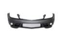
- Q: How to replace the front bumper fascia on Buick LeSabre?A:The replacement process for front bumper fascia begins with hood opening and vehicle elevation with proper support. The Fascia Retainer Remover (J 36346) helps users detach the two retaining push pins which maintain the front bumper fascia attachment to front wheelhouse extensions. Use a tool to disconnect the parking lamp electric connectors before beginning to loosen the captive stud combined with nut. Continuously tapping the captive stud and nut allows you to clear the fender keyhole slots while simultaneously freeing up the bolt enough to remove the weld nut on the fenders. The Fascia Retainer Remover (J 36346) should be used to detach five push pin retainers that secure the front bumper fascia to the upper fascia support and two push pin retainers that fasten it to the air deflector. The front bumper fascia with its attached front energy absorber from the front impact bar should be removed before detaching the energy absorber from the fascia. To install the energy absorber you first need to mount it onto the front bumper fascia before starting every fastener manually. Begin by positioning the front bumper fascia along with the front energy absorber correctly onto the front impact bar. Insert fasteners into the keyhole slots located on the front fenders. Then adjust the fasteners starting with the bolt to 9 N.m (80 lb in). Secure the front bumper fascia to the upper fascia support through push pin retainers after reattaching parking lamp electrical connectors and finally secure front bumper fascia to front wheelhouse extensions with push pin retainers.
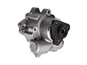
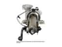
- Q: How to replace the alternator on Buick LeSabre?A:In order to replace the generator (L36), you would remove the Drive Belt and take off the battery negative cable. Next, remove the fuel injector sight shield and the screws that hold the generator brace and then the brace itself. The wiring harness connector from the generator will be disconnected and the protective boot from the generator output bat terminal repositioned for access. Unscrew the bat terminal nut off the generator output and unhook battery positive lead from the generator and after that, remove the bolts holding the generator on the vehicle to remove the generator from the vehicle. For installation, mount the generator to the engine and tighten the mounting bolts with the torque of 50 n.m (37 lb ft). Making the connection between the wiring harness connector and the generator, then the positive lead, and then the generator output bat terminal nut should be installed and tightened to 12.5 n.m (111 lb in). Reinforce the generator by applying the protective boot to the generator output bat terminal, install the generator brace and the fasteners against 50 n.m (37 lbs. Ft) and brace on 25 n.m (18 lbs. Ft.). Finally, reinstall the fuel injector sight shield, Drive Belt and bring back the battery negative cable.
- Q: How to replace the front emblem/nameplate on Buick LeSabre?A:Apply tape to cover the surface before uninstalling the emblem/nameplate. Heat up the front emblem/nameplate with J 25070 Heat Gun (J 25070) for 30 seconds while making simple circular motions. Gently take out the emblem/nameplate by sliding a plastic flat blade across its edge. Clean the surface thoroughly before installing a new emblem/nameplate according to these steps: use the 3M(TM) Scotch Brite molding adhesive remover disk (3M(TM) P/N 07502) or an equivalent to remove old adhesive from body parts; wipe plastic parts with a VMP naphtha solution or 50/50 isopropyl alcohol mix on a lint-free cloth. You need to work on a clean and dry space where you can put the emblem so its hole touches the fender surface. Heat the mounting surface to 27-41°C (80-105°F) by using J 25070 Heat Gun (J 25070). Place the emblem/nameplate under heat to get a temperature range of 29-32°C (85-90°F) while keeping it away from the adhesive side. Apply the raised edge of the emblem/nameplate against its mounting surface and stick it firmly in place by pressing down evenly across the entire surface. Finally, remove the protective tape.
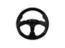
- Q: How to service and repair the steering wheel on Buick LeSabre?A:To service and repair the Steering Wheel, first disconnect the negative Battery Cable and take the sir system out of action. Take off the inflatable restraint Steering Wheel module and, if applicable, the weight block from the Steering Wheel base. Take your alignment marks off the Steering Shaft and Steering Wheel after removing the nut. Take out the steeron wheel puller legs (J42578), and the case for the Steering Wheel puller (J1859-A), and use them to pull the Steering Wheel off so that you can take these out. For installation, run the routing through the Steering Wheel, nest the marks, and put the Steering Wheel into place. Tighten the nut to 41 nm (30 ft. Lbs.) and install the weight block and the inflatable restraint a Steering Wheel module. Finally, enable the sir system.


