ChevyParts
My Garage
My Account
Cart
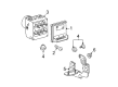
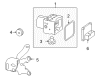
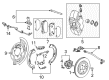
OEM Chevrolet ABS Control Module
Anti Lock Brake Control Module- Select Vehicle by Model
- Select Vehicle by VIN
Select Vehicle by Model
orMake
Model
Year
Select Vehicle by VIN
For the most accurate results, select vehicle by your VIN (Vehicle Identification Number).
487 ABS Control Modules found


Chevrolet Control Module Part Number: 20908753
$244.13 MSRP: $444.69You Save: $200.56 (46%)Ships in 1-2 Business DaysProduct Specifications- Other Name: Module, Electronic Brake Control; ABS Control Module


Chevrolet Modulator Valve Part Number: 15924821
$383.38 MSRP: $827.19You Save: $443.81 (54%)Ships in 1-2 Business DaysProduct Specifications- Other Name: Valve, Electronic Brake Control; Modulator

Chevrolet Modulator Valve Part Number: 84605924
$467.75 MSRP: $842.80You Save: $375.05 (45%)Ships in 1-3 Business DaysProduct Specifications- Other Name: Module Assembly-Electronic Brake Control (W/Brake Pressure Mode; ABS Control Unit; Module, Electronic Brake Control
- Replaced by: 85737283
- Replaces: 84092233, 84314313

Chevrolet Control Module Part Number: 23303420
$210.78 MSRP: $384.81You Save: $174.03 (46%)Ships in 1-2 Business DaysProduct Specifications- Other Name: Module Kit-Electronic Brake Control; ABS Control Module; Module; Module Kit, Electronic Brake Control
Chevrolet Control Module Part Number: 84820908
$552.95 MSRP: $996.30You Save: $443.35 (45%)Ships in 1-3 Business DaysProduct Specifications- Other Name: Module Kit-Electronic Brake Control; Module; Module Kit, Electronic Brake Control
- Replaces: 84452780

Chevrolet Control Module Part Number: 22966395
$536.28 MSRP: $1098.92You Save: $562.64 (52%)Ships in 1-2 Business DaysProduct Specifications- Other Name: Module Kit-Electronic Brake Control; ABS Control Module; Module Kit, Electronic Brake Control

Chevrolet Control Module Part Number: 84092230
$172.38 MSRP: $339.27You Save: $166.89 (50%)Ships in 1-2 Business DaysProduct Specifications- Other Name: Module, Electronic Brake Control; ABS Control Module
- Replaces: 22760041
Chevrolet Control Module Part Number: 84121202
$213.04 MSRP: $385.60You Save: $172.56 (45%)Ships in 1-2 Business DaysProduct Specifications- Other Name: Module Kit-Electronic Brake Control; ABS Control Module; Module; Module Kit, Electronic Brake Control

Chevrolet Control Module Part Number: 84726668
$426.52 MSRP: $765.05You Save: $338.53 (45%)Ships in 1-3 Business DaysProduct Specifications- Other Name: Valve Kit, Electronic Brake Control; ABS Control Module; Modulator Valve; ABS Control Unit
- Replaces: 84205178, 84056037

Chevrolet Control Module Part Number: 84031278
$315.99 MSRP: $593.41You Save: $277.42 (47%)Ships in 1-2 Business DaysProduct Specifications- Other Name: Module Kit-Electronic Brake Control; ABS Control Module; Modulator Valve; Module Kit, Electronic Brake Control

Chevrolet Control Module Part Number: 84414660
$254.58 MSRP: $460.79You Save: $206.21 (45%)Ships in 1-2 Business DaysProduct Specifications- Other Name: Module Kit-Electronic Brake Control; ABS Control Module; Module Kit, Electronic Brake Control
Chevrolet Control Module Part Number: 84166562
$320.42 MSRP: $629.38You Save: $308.96 (50%)Ships in 1-2 Business DaysProduct Specifications- Other Name: Module Kit-Electronic Brake Control; ABS Control Module; Module; Module Kit, Electronic Brake Control

Chevrolet Modulator Valve Part Number: 84831913
$326.57 MSRP: $585.79You Save: $259.22 (45%)Ships in 1-3 Business DaysProduct Specifications- Other Name: Module Assembly, Electronic Brake Control (W/Brake Pressure Mode Valve); ABS Control Module; ABS Control Unit; Module, Electronic Brake Control
- Replaces: 84121209, 84216587
Chevrolet Modulator Valve Part Number: 85161999
$414.50 MSRP: $743.50You Save: $329.00 (45%)Ships in 1-3 Business DaysProduct Specifications- Other Name: Module Assembly-Electronic Brake Control (W/Brake Pressure Mode; ABS Control Module; ABS Control Unit; Module, Electronic Brake Control
- Replaces: 23208066, 23234104, 23363175
Chevrolet Control Module Part Number: 84452779
$192.86 MSRP: $362.18You Save: $169.32 (47%)Ships in 1-2 Business DaysProduct Specifications- Other Name: Module Kit-Electronic Brake Control; ABS Control Module; Module; Module Kit, Electronic Brake Control
Chevrolet Control Module Part Number: 84092231
$169.82 MSRP: $318.92You Save: $149.10 (47%)Ships in 1-2 Business DaysProduct Specifications- Other Name: Module, Electronic Brake Control; ABS Control Module
Chevrolet Modulator Valve Part Number: 85162006
$389.96 MSRP: $710.30You Save: $320.34 (46%)Ships in 1-2 Business DaysProduct Specifications- Other Name: Module Assembly-Electronic Brake Control (W/Brake Pressure Mode; ABS Control Unit; Module, Electronic Brake Control
- Replaces: 84092232, 84605923
Chevrolet Control Module Part Number: 22961487
$235.38 MSRP: $425.99You Save: $190.61 (45%)Ships in 1-2 Business DaysProduct Specifications- Other Name: Module Kit-Electronic Brake Control; ABS Control Module; Modulator Valve; Module Kit, Electronic Brake Control

Chevrolet Modulator Valve Part Number: 19418699
$871.27 MSRP: $1566.08You Save: $694.81 (45%)Product Specifications- Other Name: Valve Assembly, Brake Pressure Mod (W/ Electronic Brake & Traction Control Module); ABS Control Module; ABS Control Unit; Valve, Electronic Brake Control
- Replaces: 92246445, 92240017

Chevrolet Control Module Part Number: 22782245
$190.54 MSRP: $341.78You Save: $151.24 (45%)Product Specifications- Other Name: Module Kit-Electronic Brake Control; ABS Control Module; Module; Module Kit, Electronic Brake Control; Module, Electronic Brake Control
| Page 1 of 25 |Next >
1-20 of 487 Results
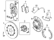
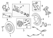
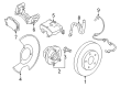
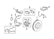
Chevrolet ABS Control Module
Want to cut long-term maintenance and repair costs? Choose OEM ABS Control Module. Those parts deliver top durability you can trust. On our site, you'll find a huge catalog of genuine Chevrolet parts. Prices are unbeatable, so you can keep more in your pocket. Every OEM Chevrolet ABS Control Module includes a manufacturer's warranty. You can also get an easy return policy that keeps buying risk free. Fast delivery, get your car on the road quickly. It's simple to search, compare, and order. Stop guessing about quality or fit. Order today and save with parts that last.
Chevrolet ABS Control Module Parts Questions & Experts Answers
- Q: How to properly handle the ABS Control Module replacement process on Chevrolet Equinox?A:Always verify that the ignition switch shows OFF before working on the ABS Control Module wiring harness to avoid ABS Control Module/EBTCM harm. The first step involves dismounting and placing aside the transmission control module (TCM) when present. Clear all visible dirt from the surroundings where the ABS Control Module and brake pressure modulator valve (BPMV) connect. Disconnect the ABS Control Module electrical connector together with the pump motor electrical connector. Unscrew the ABS Control Module attaching screws before using caution to remove the ABS Control Module from its position beside the BPMV. Before ABS Control Module installation to BPMV clean denatured alcohol must be used with a clean shop cloth to prepare the sealing surface. Next apply the ABS Control Module to the BPMV. Fasten the ABS Control Module-to-BPMV attaching screws with a 3 Nm torque setting while following a cross pattern approach. The pump motor electrical connector along with the electrical connector must be connected to the ABS Control Module. Move the TCM to its mounting bracket before switching the ignition to ON and avoiding engine start. Conduct the Diagnostic System Check - Vehicle in Vehicle DTC Information through the last step of the procedure.
- Q: How to replace the ABS Control Module on Chevrolet Colorado?A:Before ABS Control Module replacement, workers should use clean paper and shop towels for placement between the ABS Control Module assembly and inner fender. Disconnect the electrical connector from the ABS Control Module, then move it to the position behind the Brake Booster. Clean both module and master cylinder with de-natured alcohol before extracting brake pipes running between these parts. Also, pull away the rear brake pipe from cowl retaining points. Brake fluid leakage and contaminant entry will be minimized by putting rubber plugs into both the brake pressure modulator valve (BPMV) and master cylinder. The ABS Control Module extraction process starts with removing its mounting nuts followed by taking out the unit from the vehicle and positioning it on its side. The abs module requires 4 mounting screws that must be removed carefully before replacement of new screws. The abs module assembly needs replacement instead of attempting to fix damaged screws when they break during uninstallation. Use new collars to replace the 4 components which separate the ABS Control Module from the bpmv. When separating the ABS Control Module from the bpmv within the abs module, prevent the use of pry bars; if separation is impossible, then replace the abs module as a whole unit. Following ABS Control Module and bpmv separation, discard both solenoid plate and o-rings, then use a clean paper towel to clean the bpmv assembly while avoiding shop towels or brake cleaner. The examination of solenoids along with bpmv surface for signs of contamination or corrosion must lead to bpmv assembly replacement when needed. Affix the new solenoid plate with o-rings to the ABS Control Module afterward, adding the bpmv to the assembly, then secure the new collars before tightening their screws to 5 nm (44 inch lbs.) while performing a finger tighten first. The abs module installation must include a 9 nm (80 inch lbs.) torque value while tightening the mounting nuts correctly. The replacement process requires removal of rubber plugs from brake pipes and ABS Control Module assembly until you can install brake pipes onto the ABS Control Module assembly while applying 19 nm (14 ft. Lbs.) torque after initial finger tightening. The final steps require users to reconnect the electrical connector and install the rear brake pipe within the cowl retainer before they remove all paper or shop towels from between the ABS Control Module assembly and inner fender. Then the system requires abs brake bleeding to complete.
- Q: How to replace the ABS Control Module on Chevrolet Malibu?A:The replacement process for the ABS Control Module (ABSCM) should start by setting the ignition switch to OFF status to safeguard the ABSCM/EBTCM components. There must be cleaning around the ABSCM while avoiding dirt and foreign material before you remove its electrical connector. You must first remove the 4 retaining bolts of ABSCM-to-BPMV and then carefully extract the ABSCM from the BPMV position while taking out the motor pin connector because the new connector will be included with the replacement. Denatured alcohol with a clean shop cloth allows you to clean the BPMV surface while you align the ABSCM to its electrical terminals before installing it. Repeat the installation by fastening the 4 ABSCM-to-BPMV retaining bolts at 5 Nm (44 inch lbs.) using a crisscross sequence. Secure the assist locking lever after ensuring the ABSCM electrical connector insertion for preventing communication problems. Installation of a new ABSCM requires programming and execution of a programming and setup procedure with the ignition switch set to ON while avoiding engine start.


Related Chevrolet Parts
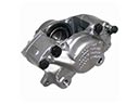 Chevrolet Brake Calipers
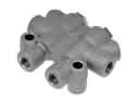 Chevrolet Brake Proportioning Valve
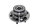 Chevrolet Wheel Hub
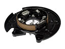 Chevrolet Brake Backing Plate
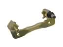 Chevrolet Brake Caliper Bracket
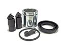 Chevrolet Brake Caliper Repair Kit
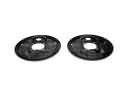 Chevrolet Brake Dust Shields
 Chevrolet Brake Fluid Level Sensor
 Chevrolet Brake Line
 Chevrolet Brake Pad
 Chevrolet Spindle Nut
 Chevrolet Wheel Bearing Dust Cap
Browse Chevrolet ABS Control Module by Models
S10 Colorado Tahoe Cruze Malibu Camaro Equinox Impala SS SSR Avalanche Silverado 1500 Silverado 2500 HD Caprice Classic Cobalt Suburban Traverse Blazer HHR Sonic Tracker Volt Spark Trax Trailblazer Astro Cavalier Corvette Aveo Beretta Bolt EUV Bolt EV C1500 C2500 C3500 Celebrity City Express Corsica Express 1500 Express 2500 Express 3500 G10 G20 G30 K1500 K2500 K3500 Lumina Metro Monte Carlo P30 Prizm S10 Blazer Silverado 2500 Uplander Venture Lumina APV Silverado 3500 Suburban 1500 Trailblazer EXT Avalanche 1500 Avalanche 2500 Aveo5 C1500 Suburban C2500 Suburban Captiva Sport Cruze Limited Impala Limited K1500 Suburban K2500 Suburban Malibu Limited Silverado 1500 Classic Silverado 1500 HD Silverado 1500 HD Classic Silverado 1500 LD Silverado 1500 LTD Silverado 2500 HD Classic Silverado 3500 Classic Silverado 3500 HD Spark EV Suburban 2500 Suburban 3500 HD